Many systems have backup components that can be switched on in the event of a failure of a primary component. There are a number of ways to model the switch to a backup component in GoldSim, but the easiest way is to make use of the StartOperating and StopOperating event outputs of the primary component.
The model file Backup.gsm, found in the Reliability Examples folder in your GoldSim directory (accessed by selecting File | Open Example... from the main menu), provides both a simple and a more advanced example of modeling the switchover from a Primary to a Backup component. In both cases, the Primary element has a normally distributed mean time to failure of 6 months, with a mean of 1 month. Failures are repaired according to a Gamma distribution with a mean of 1 month and a standard deviation The square root of the variance of a distribution. The variance is the second moment of the distribution and reflects the amount of spread or dispersion in the distribution. of 1 week. The Backup element has no failure modes.
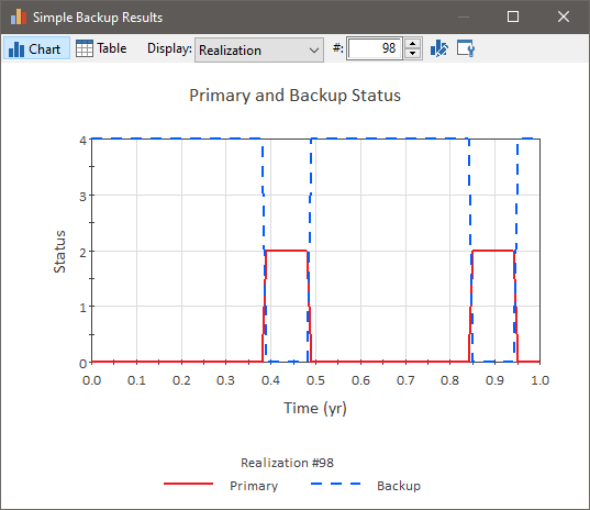
The first (top) example uses the "Stop Operating" output of the primary component to start the standby system. When the primary component is repaired, the primary component's "Start Operating" output is then used to turn the standby system back off. Because the backup component has no failure modes, it means that the backup component is always functional when the primary component fails, as shown in the time history plot of status values below:

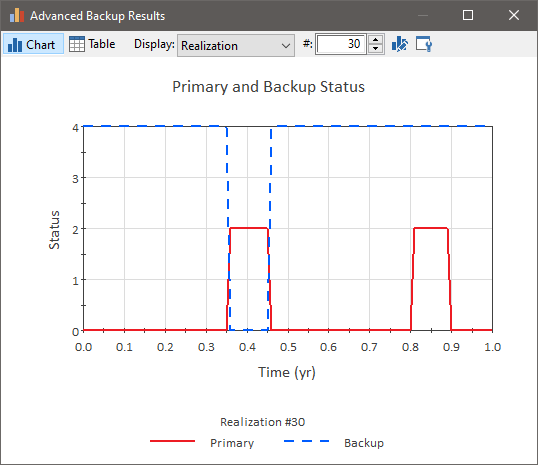
The second (bottom) example uses two Action elements to model the control system that turns the backup unit on and off. The control system has an unreliable failure mode with a Reliability of 0.9, meaning that it will successfully turn the backup on or off 9 times out of 10. The Action elements modeling the control system are still triggered by the StopOperating and StartOperating output of the element modeling the Primary system, but the Backup system's On and Off triggers are now linked to the ActionOK outputs of the two Action elements representing the control system.
With this approach, the backup can fail to start, or fail to stop when the Primary system returns to service. The plot below shows a realization A single model run within a Monte Carlo simulation. It represents one possible path the system could follow through time. where the Backup responds to the first failure correctly, but fails to start the second time the Primary component fails.

- Example: Creating User-Defined Base Variables
- Example: Handling Actions Internally
- Example: Modeling Changing Operational Environments Using Failure Mode Acceleration
- Example: Modeling Component Maintenance and Replacement
- Example: Modeling Dependencies on Other Reliability Components
- Example: Modeling Dynamic Failure Mode Behavior Such as Burn-In
- Example: Modeling Non-Fatal Failure Modes
- Example: Modeling Resource Requirements for Reliability Elements
- Example: Modeling the Switchover to a Backup Component
- Example: Understanding the Differences Between Failure Mode Base Variables
- Example: Using Custom Reliability Outputs to Report Throughput Calculations
- Example: Using Reliability Elements for a Dam Risk Assessment
- Example: Using Reliability Elements to Model Failing Pumps
- Example: Using the Reliability Element's Primary Output
- Example: Working with Internal and External Requirements