In most simple cases, the location of elements is a matter of logical organization (i.e., they should be placed where the component intuitively should be located). This works for most systems because an equivalent external and internal requirements tree will produce the same result.
The model file InternalExternal.gsm, found in the Reliability Examples folder in your GoldSim directory (accessed by selecting File | Open Example... from the main menu), shows a simple system constructed with two identical models: one with internal requirements and a second with external requirements.
In the model, the Internal_Req and External_Req elements both require that either another reliability element (Internal_Reference and External_Reference respectively) with a simple failure rate of 1/3yr is operating (or in the case of the child, operable), or that a Status element is true (the Status_Int and Status_Ext elements become true at 2.5 years).
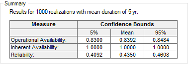
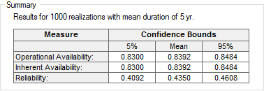
If you run the model and view plots of availability The probability that a component or system is performing its required function at any given time. and reliability in the Summary portion of the Results tab for both elements over 1000 realizations, you'll see that the results for both versions of the model are statistically identical for Reliability and Operational Availability The probability that a component will be operating at any given time.:
External Requirements:

Internal Requirements:

The Inherent Availability The probability that the component will be operable at any given time (a component that is turned off or has unmet external requirements, but is not failed is considered to be operable). differs because in the case of the External_Req element, it ceases to operate because of an external requirement. Hence, the element itself is considered operable, even though it is not operating.
There are some situations where location of a reliability element can be important. The most important of these situations are listed below:
- If Component A can operate even when Component B has failed, A cannot be a child of B (since all child elements stop operating when the parent stops operating).
- Elements that reference the locally available properties of another element as inputs (e.g. ~Status, ~Failed, ~OperatingTime and ~TotalTime), must be placed as child elements to the element they are referencing. If you try to reference these locally available properties in a peer element (i.e., without being a child), it will use its own locally available property values instead of the element of interest.
- You cannot create an external requirements reference to the child element of a peer. For example, if Component B is a system (with children B1, B2 and B2), Component A (a peer to Component B) cannot directly refer to B1, B2 or B3 in a requirements tree. Note that this does not prevent you from referencing a peer whose logic tree includes references to child elements (i.e., A could reference B as an external requirement, and B could reference B1 as an internal requirement). It only restricts direct links to a child element of a peer.
- You cannot have two peer elements dependent (directly or indirectly through an intermediate element) on each other in order to operate. Such a system would result in recursive logic.
The model file InternalExternalRestrictions.gsm, found in the Reliability Examples folder in your GoldSim directory (accessed by selecting File | Open Example... from the main menu), demonstrates some of the restrictions that may influence the decision to place elements as peers or as children. The model will walk you through attempts to violate the restrictions on referencing the child of a peer element, and will also demonstrate what will happen when you try to create a situation where two peer elements are dependent on each other in order to operate.
In addition, the model shows ways that you can work within these restrictions to create your model in cases where your system has these types of situations.
Learn more
- Example: Creating User-Defined Base Variables
- Example: Handling Actions Internally
- Example: Modeling Changing Operational Environments Using Failure Mode Acceleration
- Example: Modeling Component Maintenance and Replacement
- Example: Modeling Dependencies on Other Reliability Components
- Example: Modeling Dynamic Failure Mode Behavior Such as Burn-In
- Example: Modeling Non-Fatal Failure Modes
- Example: Modeling Resource Requirements for Reliability Elements
- Example: Modeling the Switchover to a Backup Component
- Example: Understanding the Differences Between Failure Mode Base Variables
- Example: Using Custom Reliability Outputs to Report Throughput Calculations
- Example: Using Reliability Elements for a Dam Risk Assessment
- Example: Using Reliability Elements to Model Failing Pumps
- Example: Using the Reliability Element's Primary Output
- Example: Working with Internal and External Requirements