By default, any failure modes that are added to a Reliability element are automatically added as Internal Requirements in the element's "Operating Requirements" tree. In particular, GoldSim automatically inserts a "Not" condition in the internal requirements portion of the requirements tree: Not ~Failed[n], where n is the failure mode.
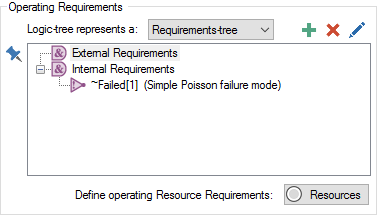
For example, when you create a new Reliability element, it automatically has a single default failure mode. Note that Not ~Failed[1] automatically is added as an Internal Requirement:

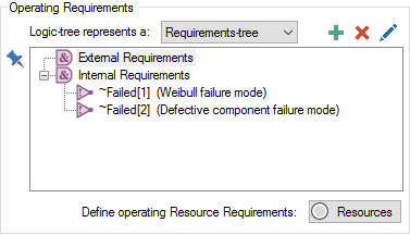
If the element had two failure modes, the Operating Requirements would look like this:

What does this Internal Requirement refer to? Recall that the Reliability element provides an output called Failed that is a vector A one-dimensional array. of ten items. It is based on an array A collection of variables that share common output attributes and can be manipulated in GoldSim elements or input expressions. label set named FailureModes (with ten items from 1 to 10) that is automatically provided by GoldSim. Each item in the vector corresponds to a failure mode defined for the element (GoldSim allows up to 10 failure modes). Failed[1] is a scalar An output consisting of a single value or condition. output that corresponds to failure mode # 1. Each item is set to True if its corresponding failure mode has occurred (and it is reset to False if the mode is repaired).
When referenced inside the element itself, however, the Failed vector must be referenced as ~Failed. ~Failed is referred to as a locally available property.
Locally available properties derive their name from the fact that they may only be available, or they may take on different values (i.e., be over-ridden), in "local" parts of your model (e.g., within a particular element, or within a particular input field for an element). Locally available properties are referenced by prefacing them with the ~ operator. Since the Failed vector is being referenced within the element, it must be referenced in the Requirements tree as a local variable.
The triangle with the ! inside represents a Not node in the tree, so Not ~Failed[1] is True if failure mode #1 has not occurred and False if it has occurred. This implies that the failure mode is assumed to be fatal to the component (i.e., if the failure mode occurs, the component itself fails and is no longer operative). That is, by default, whenever you add a failure mode, GoldSim treats it as if it is a fatal failure mode.
If desired, however, you can specify that a failure mode is non-fatal. To do so, you simply need to remove the Not node from the Requirements tree.
In this case, you will most likely want to specify that the failure, while not fatal, reduces the capacity or performance of some internal component of the system by referencing Failed[n] in an ancillary calculation (e.g., throughput).
Learn more
- Adding Failure Modes
- Changing Failure Mode Parameters Dynamically
- Failure Mode Control Variables
- Failure Modes and Internal Requirements
- Failure Modes Available for Function and Action Elements
- Failure Modes Available Only for Action Elements
- Importing Failure Mode Information from Spreadsheets
- Modeling Coupled and Non-Fatal Failure Modes
- Modeling the Repair of Failure Modes
- The Failure Modes Tab