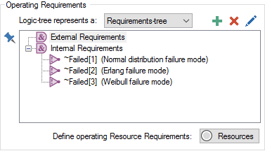
By default, any failure modes that are added to a Reliability element are automatically added as Internal Requirements in the element's "Operating Requirements" tree. In particular, GoldSim automatically inserts a "Not" condition in the internal requirements portion of the requirements tree: Not ~Failed[n], where n is the failure mode.
This implies that the failure mode is assumed to be fatal to the component (i.e., if the failure mode occurs, the component itself fails and is no longer operable). That is, by default, whenever you add a failure mode, GoldSim treats it as if it is a fatal failure mode.
In some cases, however, the failure mode may not be fatal to the component (i.e., when the failure mode occurs, it does not cause the component itself to fail). This type of situation can be modeled by simply removing references to non-fatal failure modes from the Requirements tree.
For example, let's consider a Reliability element with three failure modes. By default, when we are done adding the three failure modes, the Requirements tree will look like this:

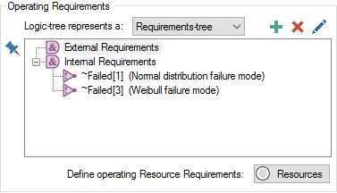
If you wanted to make the second failure mode non-fatal, you would simply select the node and press the Remove button (the red X). This would mean that the component would continue to operate if the second failure mode occurred. The Requirements tree would then look like this:

In this case, you would most likely want to specify that the failure, while not fatal, reduces the capacity or performance of some internal component of the system by referencing Failed[n] in an ancillary calculation. For example, inside the reliability element (that was modeled as a system), you may have an equation defining a throughput rate that looks like this:

Note that in this case, the failure is referenced as a local variable, since it is internal to the Reliability element.
In other cases, you may want to specify that more than one failure mode must occur to cause the component to stop operating. In this case, you can use gate nodes (an OR node in this example) to customize the failure logic.
Again, let's consider the case where a component has three failure modes. Let's assume, however, that the component fails if either 1) the third failure mode occurs, or 2) both the first and the second failure modes occur.
To represent this, we would do the following:
- Remove the first and second failure modes from the Internal Requirement list.
- Add an Or node.
- Under the Or node, add a Not node with the argument ~Failed[1].
- Under the Or node, add a Not node with the argument ~Failed[2].
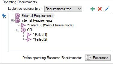
The requirements tree would then look like this:

It indicates that the requirement for the component to operate is that failure mode #3 has not occurred AND that either failure mode 1 OR failure mode 2 has not occurred.
Learn more
- Adding Failure Modes
- Changing Failure Mode Parameters Dynamically
- Failure Mode Control Variables
- Failure Modes and Internal Requirements
- Failure Modes Available for Function and Action Elements
- Failure Modes Available Only for Action Elements
- Importing Failure Mode Information from Spreadsheets
- Modeling Coupled and Non-Fatal Failure Modes
- Modeling the Repair of Failure Modes
- The Failure Modes Tab