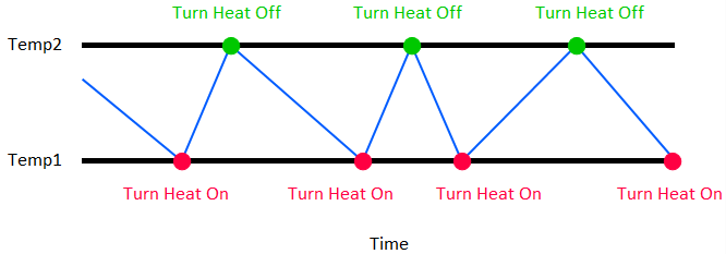
A Deadband Controller produces an output that switches abruptly between two states: a specified (generally fixed) flow or zero flow. This is how a simple thermostat works. A thermostat monitors temperature (a proxy for heat, which is a state variable The output of an element in GoldSim whose value is computed based on the historical value of the element’s inputs (as opposed to only being a function of the current value of the element’s inputs). State variables have well-defined initial conditions. Feedback loops can only be created if they contain at least one state variable.). It then turns the furnace blower on when the temperature drops to a certain value (Temp1) and turns the furnace blower off when the temperature raises to a certain value (Temp2):

Note that in this example, since we are adding heat (i.e., there is an inflow of heat to the system), this is an Inflow Controller.
When you select “Deadband” as the Method, the first thing you must do is specify how you are going to define the inputs:
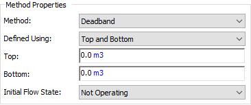
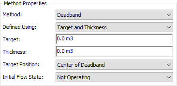
Defined Using: There are two choices: “Top and Bottom” (in which you specify the top of the dead band and the bottom of the dead band); and “Target and Thickness” (in which you specify a target and a dead band thickness around that target).
If “Top and Bottom” are selected, there are two key inputs that must be provided:

Top: This is the top of the range over which the process variable is controlled. In the example above, this would be Temp2 (the difference between Temp2 and Temp1 is referred to as the is the deadband) As such, it has the same dimensions An output attribute for an element that defines the dimensionality (in terms of Length, Time and other fundamental dimensions) of the output. as the process variable (and hence must have the same dimensions as the Flow Units * Time). While this is often constant, it can be specified to change with time.
Bottom: This is the bottom of the range over which the process variable is controlled. In the example above, this would be Temp1 (the difference between Temp2 and Temp1 is referred to as the is the deadband) As such, it has the same dimensions as the process variable (and hence must have the same dimensions as the Flow Units * Time). While this is often constant, it can be specified to change with time.
If “Target and Thickness” are selected, there are three key inputs that must be provided:

Target: This is the desired value of the process variable. Hence, it must have the same dimensions as the process variable (Flow Units * Time). While the Target is often constant, it can be specified to change with time.
Thickness: This is the size of the range between which the process variable is controlled. In the example above, the difference between Temp2 and Temp1 is the deadband Thickness. As such, it has the same dimensions as the process variable (and hence must have the same dimensions as the Flow Units * Time). It must be a positive value. Although it can be specified to vary with time, this would be unusual.
Target Position: This is the position of the Target relative to the deadband. It is either “Top of Deadband”, “Center of Deadband” or “Bottom of Deadband”. That is, the Target can be defined as being centered in the deadband (i.e., in the is example above, the target would be halfway between Temp1 and Temp2), at the top of the deadband (i.e., the target would be Temp2) or at the bottom of the deadband (i.e., the target would be Temp1).
For Inflow Controllers, when the process variable reaches the bottom of the deadband, the output is set to the Flow Capacity (i.e., the Controller is “operating”). When the process variable reaches the top of the dead band, the output is set to zero (i.e., the Controller is “not operating”). Similarly, for Outflow Controllers, when the process variable reaches the top of the deadband, the output is set to the Flow Capacity (i.e., the Controller is “operating”). When the process variable reaches the bottom of the dead band, the output is set to zero (i.e., the Controller is “not operating”).
Under what circumstances would you use one way of defining a Deadband Controller over another? In most cases, it is just a matter of preference. However, there is one important case where one way of defining a Deadband Controller is much easier than the other. In particular, if you want to use a proxy (e.g., elevation) for your Process Variable (e.g., volume) when defining the Controller and the conversion between the proxy and the Process Variable is not constant (e.g., a pond that with walls that were not vertical), you should use the “Top and Bottom” method.
Note that in order to fully define the behavior of the Deadband Controller, an additional input is required:
Initial Flow State: This determines whether or not the Controller output is operating (i.e., equal to Flow Capacity) at the start of the simulation when the initial value of the process variable falls within the deadband. Note that if the initial value of the process variable is outside of (or on the edge of) the deadband, then this input is ignored and whether or not the flow is initially operating (set to Flow Capacity) or not operating (set to zero) is automatically determined as follows:
- For Outflow Controllers:
- If the initial value of the process variable is above the dead band, the flow is operating.
- If the initial value of the process variable is below the dead band, the flow is not operating.
- For Inflow Controllers:
- If the initial value of the process variable is above the dead band, the flow is not operating.
- If the initial value of the process variable is below the dead band, the flow is operating.
Deadband Controllers result in a process variable the oscillates between the bottom of the deadband and the top of the deadband. The smaller the deadband (and the higher the Flow Capacity), the more frequent the oscillations. As a result, the deadband is typically defined to be large enough to limit the frequency of oscillations.
It is important to note, however, that the process variable does not necessarily stay within the deadband. In the thermostat example discussed above, when the temperature drops to Temp1, the furnace is turned on, but depending on how fast the house is losing heat, the temperature may continue to drop for some time until the inflow of heat from the furnace catches up to the heat loss and starts to raise the temperature. Of course, if the flow of heat into the house does not eventually exceed the heat loss, the temperature would continue to drop below the bottom of deadband (indicating that you need a bigger furnace or more insulation).
There is also a critical computational issue that is important to understand when using a Deadband Controller with regard to how fast the system responds: when does GoldSim “notice” that the process variable reaches a boundary of the deadband? If the process variable is a state variable (which should typically be the case), GoldSim is able to insert an unscheduled update (i.e., timestep A discrete interval of time used in dynamic simulations.) exactly at the point in time when the boundary is reached. However, if the process variable is not a state variable, GoldSim can only check to see if the process variable has reached the boundary at the scheduled timesteps Timesteps that are directly specified by the user prior to running the model.. Hence, it may not be able to respond (e.g., by turning on or off the flow) until the process variable has moved well outside of the deadband. This means that the performance of the Deadband Controller when the process variable is a state variable is independent of the scheduled timestep length, whereas the performance of the Deadband Controller when the process variable is not a state variable is strongly dependent on the timestep length.
Learn more
- Basic Controller Inputs
- Browser View of a Controller
- Comparing the Different Methods: Which Type of Controller Should I Use?
- Constraints on the Output of Controllers
- Controlling a Process Using Multiple Controllers
- Defining a Deadband Controller
- Defining a Proportional Controller
- Defining a Proportional Integral Derivative (PID) Controller
- Defining a Target that Represents an Upper or Lower Limit
- Turning a Controller On and Off
- Understanding Controllers
- Using a Proxy for the Process Variable When Defining a Controller
- Using Controller Elements