In nearly all multi-component systems, logical
relationships will exist between the components (e.g., "in order for component A
to operate, component B or component C must be operating"). These
relationships can be represented within the reliability elements by defining either a
In the case of the Computer element discussed in the previous
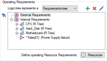
GoldSim can easily represent these relationships, but it provides a slightly different approach to fault trees than many reliability engineers will be used to. In particular, there is no need to develop a "global" requirements- or fault- tree for the entire system. The user is only required to define the immediate relationships between components. In this case, the computer's requirements tree would include four nodes, indicating that in order for the Computer to operate, the CPU, Hard Disk and Motherboard must all be operating, and the Computer itself must not have failed due to the Power Supply failure mode:

Note that these are listed as "Internal Requirements" because the components and the failure mode are internal to the Computer. Failure modes for the Computer itself are added automatically to this list by GoldSim. Any sub-components need to be added manually (as appropriate).
"External Requirements" can be used to specify requirements external to the Computer (e.g., that electricity is available).
After we build a model, we can run it. We will discuss that in the next
- Adding Failure Modes to a Reliability Element
- Documenting Your Reliability Model
- Modeling Hierarchical Systems of Components
- Representing Logical Relationships Between Components
- The Reliability Elements
- Top-Down Modeling Using the Reliability Module
- Using GoldSim's Probabilistic Simulation Engine
- Viewing and Analyzing Results