In the previous
Because GoldSim and the Reliability Module are hierarchical by nature, we can quickly transform our simple single element model into a system with a number of subcomponents. Again, the intention is to allow our model to evolve (and hopefully improve) as the system becomes better quantified.
In this case, we can convert the model of the computer into a system with child (sub) elements. (On the main page of the Function dialog, there is an option to Model this Function component as a system with child elements). When we do this, there is a slight change in the appearance of the Computer element:

A small red triangle now appears in the upper left-hand
corner of the element, and clicking on this takes you into a new layer of the
model within the computer. If you are familiar with GoldSim, you
will recognize this triangle as the same symbol that normally appears on GoldSim
Container An element that acts like a "box" or a "folder" into which other elements can be placed. It can be used to create hierarchical models. elements. In fact, when we convert a reliability element into a
system, the element retains all of its properties, but now also functions as a
Container. (In fact, it actually becomes a
In our example, we might choose to place a CPU, a Motherboard and a Hard Disk inside the Computer element, and model each of these components in as much detail as we wish:

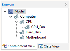
Note, however, we are not limited to one level of hierarchy in GoldSim. In fact, we can create an unlimited number of subcontainers (subcomponents). In the figure below, a browser An alternative view of a GoldSim model, in which elements are displayed in a tree, and organized either hierarchically, or by type. view of the model is provided, showing the hierarchy of components. In this case, a Function element representing a CPU Fan has been placed inside the CPU Function element, adding another level to the model hierarchy:

Of course, each of these subcomponents can have its own failure modes.
What are the benefits of using hierarchical modeling in order to model a reliability system? The most obvious is that it makes the model much more intuitive and easy to browse. If we use hierarchical modeling, we have just one element in the top level of the model for the computer, where we would otherwise have five. While this may be a subtle distinction with just one computer, it is a feature which becomes very valuable when one needs to model a bank of 50 computer servers.
In addition, due to the logical relationships that exist
between components that are actually hierarchical in the real world (e.g., a
computer contains a CPU which contains a CPU fan), it may not be possible to
represent some kinds of systems in a realistic or straightforward manner without
defining such a hierarchy. This is discussed further in the next
- Adding Failure Modes to a Reliability Element
- Documenting Your Reliability Model
- Modeling Hierarchical Systems of Components
- Representing Logical Relationships Between Components
- The Reliability Elements
- Top-Down Modeling Using the Reliability Module
- Using GoldSim's Probabilistic Simulation Engine
- Viewing and Analyzing Results