Comparison of Aquifers and Pipes for Simulating a One-Dimensional Pathway
Pipe and Aquifer elements both provide a way to simulate one-dimensional pathways (such as aquifers or rivers).
Although Aquifers and Pipes solve the same equation (using different methods), the boundary conditions that are applied at the end of the pathway differ, and this can cause differences in their results.
Aquifers can be assigned one of two boundary conditions:
- No dispersive/diffusive outflux allowed (only advection). This is the default option.
- Dispersive/diffusive outflux allowed, assuming a zero concentration in the receiving pathway. This would be appropriate, for example, if the downstream pathway represents a rapidly-flowing, "clean" pathway.
These two boundary condition options represent two possible extremes for the behavior of the system. The actual behavior of most real-world systems would be somewhere between these two extremes, although probably closer to either one or the other).
The boundary condition for the Pipe, on the other hand, is as follows:
- Concentration goes to 0 as x goes to ∞.
Effectively, this allowsdispersive/diffusive outfluxes, with a downstream concentration (immediately after the Pipe) that is not set to zero (as is the case for the Aquifer), but is actually quite close to the concentration in the Pipe (resulting in a low dispersive outflux).
If you think carefully about this, you will realize that the Pipe boundary condition actually is close (but not identical) to the default Aquifer boundary condition (no dispersive flux).
To see this, let's examine the breakthrough curves for one-dimensional pathways simulated using a Pipe and two different Aquifers (representing both boundary conditions).
The pathway is 50 m long, has a cross-sectional area of 1 m2, a dispersivity of 5 m, and a flow rate of 1 m3/day. The pathway is filled with a porous medium with a porosity of 0.3. At the upstream end, mass is added at a constant concentration of 1 mg/l. The Aquifer is based on 100 Cells, and the Pipe is solved using High Precision. This particular example model, PathwayComparison.gsm, can be found in the Contaminant Transport Examples folder in your GoldSim directory (accessed by selecting File | Open Example... from the main menu).
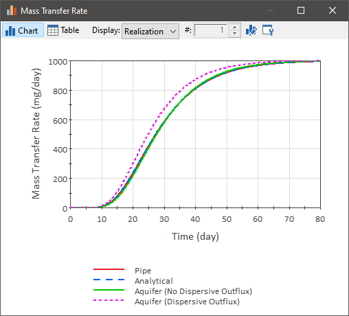
A comparison of breakthrough curves for these three cases is shown below:

Note: This plot also includes the analytical solution (Ogata and Banks, 1961), which has the same downstream boundary condition as the Pipe.The upstream boundary condition is close, but not completely identical to that for the Pipe or Aquifer, but at a sufficient distance any impacts are insignificant.
Akio Ogata and R.B Banks, 1961, "A Solution of the Differential Equation of Longitudinal Dispersion in Porous Media", Geological Survey Professional Paper 411-A (https://pubs.usgs.gov/pp/0411a/report.pdf).
As can be seen, the analytical solution, the Pipe result and the Aquifer result assuming no dispersive outfluxes are essentially identical. The Aquifer result that allows dispersive outfluxes results in a faster breakthrough, however, since the zero concentration boundary condition that is assumed in the downstream pathway artificially increases the dispersive outflux (and would only be appropriate if the downstream pathway did in fact have a very low concentration due to rapid flushing).
Therefore, since the results in this simple case are similar, under what circumstances should one pathway be used instead of the other? Some general rules are provided below:
- If solubility limits are being approached within the pathway, you should use an Aquifer.
- If the pathways (or solute) properties, including flow rates, are changing significantly over the simulation, you should use an Aquifer.
- If you need to simulate processes that occur in fractured rock masses, such as matrix diffusion, you should use a Pipe.
Moreover, when using an Aquifer, the default boundary condition (no dispersive outfluxes) should be used unless the downstream pathway can in fact be assumed to be at a very low concentration relative to the concentration leaving the pathway (e.g., due to rapid flushing).
- Advective-Dispersive Transport in Pipes
- Aquifer Pathway Example: Advection, Retardation and Dispersion
- Aquifer Pathway Outputs
- Comparing Pipes and Aquifers
- Computing Pipe and Aquifer Pathway Concentrations Accounting for Transverse Dispersion
- Controlling the Pipe Solution Algorithm
- Defining a Sorptive Coating Material for a Pipe
- Defining Basic Aquifer Properties
- Defining Basic Pipe Properties
- Features and Capabilities of Aquifers
- Features and Capabilities of Pipes
- Flux Links to/from Aquifers
- Flux Links to/from Pipes
- Pipe Pathway Outputs
- Saving Results for a Pipe
- Saving Results for an Aquifer
- Simulating Discrete Changes to the Mass Inventory in an Aquifer
- Simulating Storage Zones in a Pipe
- Simulating Suspended Solids in a Pipe
- Simulating Suspended Solids in an Aquifer
- Simulating Time-Variable Pipe Properties
- Summary of Limitations on the Use of Pipe Pathways
- Understanding How an Aquifer Pathway Works
- Viewing a Pipe in the Browser
- Viewing an Aquifer in the Browser