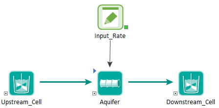
An Aquifer pathway A transport pathway element that is intended to represent a feature that essentially behaves as a fluid conduit. Internally, an Aquifer pathway actually performs its computations by creating a temporary set of linked Cell elements during the simulation. actually performs its computations by creating a temporary set of linked Cell elements during the simulation (while in Run Mode), which are subsequently removed at the end of the simulation. However, while in Run Mode The state of a model when it is running., the pathways exist (and if you pause the model, can actually be viewed).
In most cases, there is no need for you to be aware of how
this is done, or to view the temporary Cell pathways that are created. For those
that are interested, however, this
To illustrate this, and to explain how the various inputs for an Aquifer are mapped onto and treated within the temporary Cell network, we will consider a simple example. In this example, an Aquifer has been defined. Its key properties are as follows:
- The Number of Cells used to discretize the pathway is equal to five.
- The Aquifer contains an Infill Medium (Sand).
- The Aquifer has a single outflow (Q) to a downstream Cell.
While in Run Mode, an Aquifer pathway takes on some characteristics of a Container An element that acts like a "box" or a "folder" into which other elements can be placed. It can be used to create hierarchical models. so that the temporary Cells can be viewed. In this example, if we pause the model during the simulation, the Aquifer pathway will look like this (i.e., like a Container, it has a small triangle in the upper left-hand corner of the element indicating that you can "look inside"):

If we click on the triangle to "look inside" the Aquifer, we see the following:

As can be seen, five temporary Cells have been created (named "_pathwayname_Celln"). Opening the first Cell, we can see how the Media Materials (such as water, sand, clay, air) that constitute (are contained within) transport pathways. GoldSim provides two types of elements for defining media: Fluids and Solids. are defined:

The media quantities are automatically computed based on the Aquifer properties (e.g., Length, Area, Saturation, Number of Cells) and media properties (density, porosity).
In effect, GoldSim has discretized the system into these five finite volumes.
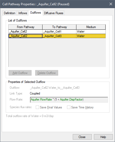
To simulate advection and dispersion/diffusion through the linked Cells, GoldSim automatically creates a number of advective and diffusive flux links. For example, here is the Outflows tab from the second Cell:

There is an Outflow from Cell2 to Cell3. Note, however, that the Flow Rate that was specified when defining the element has been adjusted. The Flow Rate (downstream) from Cell2 to Cell3 is now defined as Q*(1+DispFactor), where
DispFactor = (n α / L) - 0.5
In this equation, α is the specified dispersivity (dimensions An output attribute for an element that defines the dimensionality (in terms of Length, Time and other fundamental dimensions) of the output. of L), L is the pathway length (dimensions of L), and n is the number of cells.
Note that there is another Outflow in the Outflows tab, and it is from Cell2 to Cell1 (upstream!). If we were to look at this, we would see that this upstream Flow Rate was defined as Q*DispFactor. That is, in addition to the downstream flow that we would expect (Q), GoldSim has added two "fictitious" flows equal to Q*DispFactor (one upstream and one downstream). Note that since one fictitious flow is downgradient and one is upgradient, the net of these two flows is zero. However, they have the effect of representing longitudinal dispersion in the pathway.
In effect, what GoldSim is doing is using the Cells (the finite volumes) to solve the governing equation describing one-dimensional advective/dispersive transport. We can solve this equation numerically using finite differences. When we do so, we find that the rate of change of mass in, for example, Cell2, accounting for both advection and dispersion, can be approximated as follows:
Mass Rate of Change in Cell2 = - Q*C2*(1 + 2*DispFactor) + Q*C1*(1 + DispFactor) + Q*C3*DispFactor
where:
Q is the specified flow rate in
the Aquifer;
C1 is the concentration in
Cell1;
C2 is the concentration in Cell2;
and
C3 is the concentration in
Cell3.
The derivation of this finite difference approximation is
provided in
We can now see what the various Outflows that GoldSim automatically created represent. The first term represents the mass flows leaving Cell2. This consists of the advective flow downstream to Cell3 (equal to Q*C2) and two dispersive flows (equal to Q*C2*DispFactor), one upstream to Cell2 and one downstream to Cell3.
The second term is the mass flow entering Cell2 from Cell1 (an advective flow equal to Q*C1 and a dispersive flow equal to Q*C1*DispFactor).
The third term is the mass flow entering Cell2 from Cell3 (a dispersive flow equal to Q*C3*DispFactor).
Note: Even in the absence of the dispersive terms, a network of linked Cells simulating advective transport will inevitably exhibit a degree of numerical dispersion that is a function of the number of Cells (the degree of discretization). In particular, the equivalent numerical dispersivity is equal to L/2n. As a result, if the number of Cells is less than the pathway length divided by twice the dispersivity, that is, n<L/(2α), then the numerical dispersivity will exceed the specified dispersivity. If this occurs, GoldSim records a warning in the Run Log Text that is stored with a GoldSim model once it has been run. It contains basic information regarding the simulation, and any warning or error messages that were generated. (indicating that you either need to use more Cells or increase the dispersivity to accurately model longitudinal dispersion along the pathway).
GoldSim also automatically adds diffusive connections between the Cells to account for diffusion through the pathway (which in most cases is likely to be negligible).
Several other details should also be noted regarding how the temporary Cells are defined:
- All mass input to the Aquifer pathway (advective inflows, diffusive influxes, boundary conditions and discrete changes) are "lumped" together and treated as a Cumulative Input to the first Cell. The one exception to this rule is if a non-zero Source Term Length is specified. In this case, the mass is spread uniformly over the Cells representing the Source Term.
- By default, the temporary Cells are all of the same size. However, if a non-zero Source Term Length is defined, the size of the Cells are adjusted so that the Source Zone is accurately represented. In particular, the boundary of the Cell closest to the edge of the Zone is moved, and then all of the Source Cells upstream of the boundary are adjusted and assigned equal sizes. The remainder of the pathway (downstream of the Source Zone) is then divided equally among the remaining Cells.
- The user controls whether in addition to the advective outflux there is a dispersive/diffusive component of mass transport from the Aquifer to the receiving pathway(s), via the checkbox Enable dispersive and diffusive outfluxes to downstream pathway(s)on the element's property page. The default behavior does not include such fluxes (the check box is cleared), and only allows for advective transport out of the pathway. Note, however, that it does include diffusion and dispersion (if specified) along the length of the pathway. If the dispersive/diffusive discharge component is enabled it assumes a concentration of zero in the receiving pathway, which is generally a good approximation only if the pathway represents a rapidly-flowing "clean" aquifer or surface water pathway. Note that this mechanism can increase the outflux rate significantly for diffusively-dominated systems.
- If the pathway length changes by more than a small amount (one part in one thousand) during a simulation (e.g., due to erosion) then the existing Cell elements are modified to reflect the new geometry, and the distribution of contaminant masses is mapped onto the new geometry. This approach works for either shortening or lengthening of the pathway. When the pathway is shortened, the mass that was present in the truncated portion of the pathway is treated as part of the outflux for the corresponding time step.
Note: When the pathway's length changes, there may be some irregularities in the outflux rates due to mapping of the prior spatial distribution of species The chemical (or non-chemical, such as bacterial or viral) constituents that are stored and transported through an environmental system in a contaminant transport model. In GoldSim, the Species element defines all of the contaminant species being simulated (and their properties). masses onto the new Cell geometry. In general, users should use a larger number of Cells when modeling varying-length Aquifer pathways.
Once the model enters Result Mode The state of a model when it has been run and contains simulation results for a single set of input parameters., the temporary Cells are removed and can no longer be viewed.
When viewing the results of an Aquifer, the Mass in Pathway output represents the total mass in the pathway (the sum of the masses in all temporary Cells); the Concentration output represents the concentration in the Reference Fluid A special type of Fluid element that provides a basis for defining partition coefficients between media for the various species in the model (i.e., the ratio of the species’ concentration in the medium to its concentration in the Reference Fluid at equilibrium). in the final temporary Cell. If a suspended solid is present, the concentration represents the total concentration (including the load on suspended solids).
- Aquifer Pathway Example: Advection, Retardation and Dispersion
- Aquifer Pathway Outputs
- Comparing Pipes and Aquifers
- Computing Pipe and Aquifer Pathway Concentrations Accounting for Transverse Dispersion
- Defining Basic Aquifer Properties
- Features and Capabilities of Aquifers
- Flux Links to/from Aquifers
- Saving Results for an Aquifer
- Simulating Discrete Changes to the Mass Inventory in an Aquifer
- Simulating Suspended Solids in an Aquifer
- Understanding How an Aquifer Pathway Works
- Viewing an Aquifer in the Browser