Integrator elements can be instantaneously impacted by a discrete change signal A discrete signal that contains information regarding the response to an event..
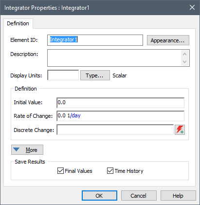
The Integrator dialog has a special input field for accepting a discrete change signal:

The Discrete Change input only accepts discrete change signals. The dimensions and order of the discrete change signals must be the same as those of the Integrator.
When an Integrator receives a discrete change signal with an Add instruction, it instantaneously adds the value of the signal to the Current Value of the Integrator. When an Integrator receives a discrete change signal with a Replace instruction, it instantaneously replaces the Current Value of the Integrator with the value of the signal.
An Integrator can also accept a discrete change signal with a Push instruction, which facilitates the modeling of aging chains.
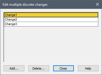
An Integrator can accept multiple discrete changes. This is indicated in the input field by separating the individual discrete change signals by semi-colons (e.g., Change1; Change2; Change3). You can also specify the multiple discrete changes using the Multiple Discrete Signals button:

Pressing this button displays a table listing the multiple discrete change signals:

A simple (and fun) application of Discrete Change elements, simulating a bouncing ball (Bounce.gsm), is included in the General Examples folder of your GoldSim directory (accessed by selecting File | Open Example... from the main menu).