The editing dialog for an External element is shown below:
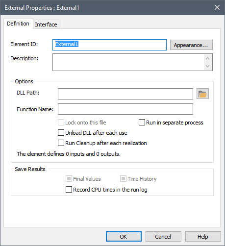
In order to use an External element, you must first specify the DLL Path and Function Name within the DLL that the element will utilize:
DLL Path: This is the name of the dynamic link library containing the external function. You can press the Browse button (the folder to the right of the DLL Path field) to search for the file. In general, you should specify the full path to the DLL. (If you specify just the filename, it will look for the DLL only in the working directory containing the GoldSim model file). Note that a single DLL can contain multiple external functions User-defined modules that can be linked to GoldSim at runtime as Dynamic Link Libraries (DLLs)..
Note: If the DLL references any external files and it is run in a separate process, it will look for those files in the folder where the DLL resides. If it is not run in a separate process, it will look for the files in the folder where the model file resides.
Function Name: This is the specific name of the external function in the DLL. This name is case-sensitive and must exactly match the name of the function in the source code for the external function.
There are also several options that control how the DLL is called by GoldSim:
Unload DLL after each use: If this box is checked, GoldSim will unload the DLL (and continue the simulation). This is useful when running very large model files (in which the DLL only needs to be called infrequently). If the DLL is subsequently called again, GoldSim will automatically reload it.
Run Cleanup after each realization A single model run within a Monte Carlo simulation. It represents one possible path the system could follow through time.: If this box is checked, GoldSim will call the DLL with a cleanup instruction (99) at the end of each realization. This is discussed in detail in Appendix C of the GoldSim User’s Guide.
Lock onto this file: If this box is checked, GoldSim regards various properties of the file to determine whether the file contents have changed.
Run in separate process: If this box is checked, GoldSim executes the DLL outside of the GoldSim process space. This can be useful for DLLs that have large memory requirements.
Note: You can use GoldSim's File element An element whose purpose is to simply control copies of auxiliary files that may be required by External elements and Spreadsheet elements. to automatically copy the DLL file from some location (typically on a network) to your machine. Because GoldSim records this action in the Run Log Text that is stored with a GoldSim model once it has been run. It contains basic information regarding the simulation, and any warning or error messages that were generated., it can provide an "audit trail" to ensure that the proper version of an external file (such as a DLL) was used in a particular simulation.
If you check the Record CPU times in the run log box, if the element uses more than 1 CPU seconds, a message will be written to the GoldSim run log identifying the element's name, type (i.e., External), the number of times it was updated, and the total CPU time used.
You define the input and output arguments for the External element via the Interface tab:
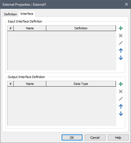
The top part of this dialog is used to define the input arguments. The bottom portion is used to define the output arguments.
In order to add an input argument, press the Add button in the Input Interface portion of the dialog:

When you do this, GoldSim displays the Insert Link dialog, allowing you to select an existing output to add to the interface). After selecting a output, the following dialog is displayed:
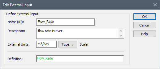
The Definition displays the output that was selected. The Name (ID) defaults to the output name. The Name (ID) will appear on the input interface for the External element (accessed via the input port). The Description is optional and simply provides additional information regarding the input argument (it defaults to the element description for the output that was selected).
Before sending the input to the DLL, GoldSim converts the value to the External Units (the units themselves are not sent to the DLL, just the value). The External Units and Type... (e.g., value/condition, scalar An output consisting of a single value or condition./vector A one-dimensional array./matrix A two-dimensional array.) for the input argument are automatically determined by the output that was selected and linked to. Moreover, the External Units themselves default to the Display Units The units (e.g., m, g, $/day) in which an output is displayed within GoldSim. for the linked output. Of course, the DLL may require that the value be sent to it assuming different units. Hence, you can edit the External Units specified (but, of course, these must have dimensions An output attribute for an element that defines the dimensionality (in terms of Length, Time and other fundamental dimensions) of the output. consistent with the Definition).
Note: If you send an output whose Type is a Condition to an external function, GoldSim will automatically convert it to either a 0 (for False) or 1 (for True) prior to sending the argument to the DLL.
Note: If you pressed Cancel (rather than selecting an output) when adding the input argument, the Definition (and hence External Units and Type) will be blank. You could enter any expression into the Definition field (including constants). The External Units and Type would need to be specified in a manner that was consistent with the Definition.
Note: In addition to reading in Values or Conditions, an External function can also read in (and subsequently output) a Time Series Definition.
In order to add an output argument, press the Add button in the Output Interface portion of the dialog:

When you do this, GoldSim displays the following dialog:
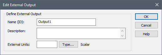
The Name (ID) is the name by which the output variable can be referenced in the model. For example, if the name of the External element was X, and the name of the output was Y, the output could be referenced as X.Y. This ID has the same restrictions as an element ID.
The Description is an optional description of the output. The External Units represent the units in which the External function returns the value. The specified units also become the display units for the output. The Type... button is used to access a dialog for specifying the data type (e.g., value/condition, scalar/vector/matrix).
Note: If you add an output whose Type is a Condition to the output interface, GoldSim will treat any non-zero number as True, and zero as False.
In addition to defining the output as a Value or a Condition, the output can also represent either a Lookup Table or a Time Series:
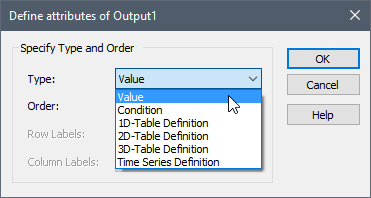
There is no limit to the number of input and output arguments that can be added.
After adding the input and output arguments, the Interface tab displays them as follows:
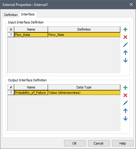
The input arguments and output arguments are transferred between GoldSim and the external function in exactly the order in which they are listed on the Interface tab.
Buttons for deleting, editing and moving the input and output arguments up and down in the list are available directly below the Add buttons.
Learn more
- Defining a Lookup Table Using an External Function
- Defining the External Element
- Exporting the External Element Interface
- External (DLL) Elements
- Implementing the External Module
- Locking onto a DLL File
- Running the DLL in a Separate Process
- Saving External Element Outputs
- Using an External Element to Define Lookup Tables
- Using an External Element to Read and/or Output Time Series
- Viewing an External Element in the Browser
- When is the External Element Called?