Some types of systems can exhibit oscillatory behavior, showing repetitive variation about a central value or between two or more different states. In some cases, this behavior is real. A pendulum is the classic example of such a system. It is also possible, however, to create logic that results in unrealistic oscillatory behavior. Most commonly, poor logic defining the Inflows and the Outflow Requests for a Pool can cause it to oscillate in an unrealistic manner.
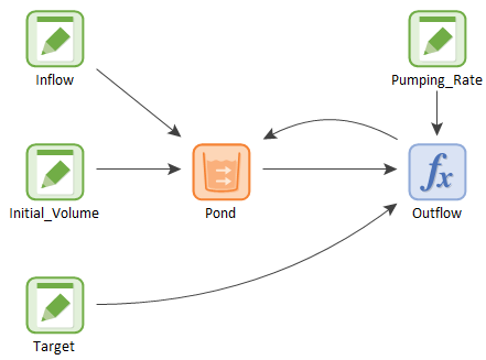
To illustrate this, let’s consider the example pictured below:

In this simple model, water flows into a pond at a constant rate (100 m3/day), and we wish to actively control the volume of water in the pond (maintaining a target volume of 300 m3) by turning a pump (that removes water from the pond) on and off in a specified manner. The pump, when on, pumps at a rate of 200 m3/day.
The (single) Outflow Request from the pond is defined as follows:

That is, when the pond volume is greater than or equal to the target volume, the pump is turned on. When it is below the target volume, it is turned off. Note that the Pumping_Rate is larger than the Inflow, so when the pump is turned on, the volume in the pond is reduced. This creates a feedback loop between the pond volume and the outflow – it is an active feedback control system that is analogous to those common in many engineered systems.
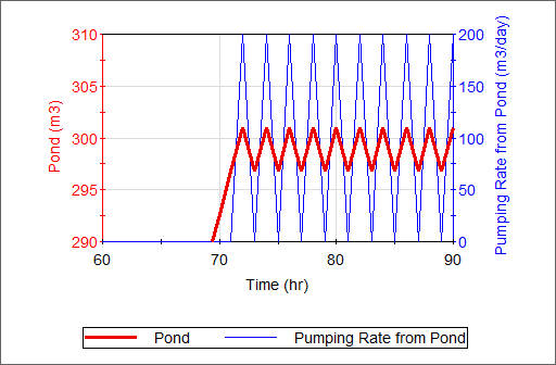
But will this logic work? At first glance, it seems to make sense, but if you were run the model and look at the results, you would quickly realize that a real system would be unlikely to be controlled by logic like this. The result looks like this:

As you can see, the pond fills up, and then oscillates right around 300 m3. As soon as it reaches the target, the pump turns on, the volume is reduced and the pump turns off, and so on. The timestep for this model is 1 hr, and the model oscillates back and forth every hour. In fact, if we reduced the timestep to 1 minute, as long as the pumping rate is high enough (and it is), it would oscillate every minute! Clearly, the system would never be designed to operate like this in the real world (e.g., the pump would not last very long if it was turned on and off every minute).
In this example, the goal is to control the Pool around a particular “target” level. Although this is a common objective (e.g., a thermostat), it is also quite common for feedback control systems like this to be used to control the behavior of a system as it approaches its bounds (and these are the situations most likely to result in oscillatory behavior). In this case, you can imagine the need to actively adjust flows as the volume approaches the bounds. Using similar logic as above, you might choose to turn off the pump when the pond empties and turn it on as soon as it exceeds zero:

Unfortunately, such logic will often cause the model to oscillate even more rapidly than in the previous example. This is because GoldSim inserts unscheduled updates whenever a bound is reached. Logic such as this could result in the Pool continuously oscillating at the bound (with a timestep being inserted each time the bound is reached). This can result in timesteps being inserted practically continuously (e.g., every second or less)!
So what is the proper way to model these kinds of systems? The key is to build logic that is realistic (i.e., logic that could actually be practically implemented in the real world). For example, if you really did want to manage a Pool to a target, what you would likely do is use what is referred to as a “deadband” or a target range within which the system is controlled. This is actually how a thermostat typically works (e.g., “turn the heat on when the temperature is 68 degrees and turn it off when it reaches 70 degrees”). You could implement this in GoldSim using a Status element.
When trying to control the behavior of a system as it approaches its bounds (as pointed out above, often the situations most likely to result in oscillatory behavior), it becomes particularly important to model the system realistically. In particular, inflows and outflows should either 1) be changed abruptly before the bound is reached (e.g., a pump turns off when the water level drops to a certain level but before the pond is actually empty); or 2) gradually ramped down such that when the Pool reaches its bound, the inflows and outflows have gradually changed to the appropriate value (e.g., gradually ramp the outflow rate down as the volume decreases until it reaches zero when the volume reaches the lower bound). If using the first approach, you would also likely implement a deadband, so that, for example, the pump turns off when the water level drops to a certain level (but before the pond is actually empty), and turns back on at some higher level.
An example model which illustrates the use of a deadband in a Pool element (PoolAdvanced.gsm) can be found in the General Examples/Stocks folder in your GoldSim directory (accessed by selecting File | Open Example... from the main menu).
Learn more about: