The logic tree dialog allows you to edit the logic trees of other reliability elements that are linked using RL Component nodes to the logic tree being edited.
To illustrate this, consider a simple example in which a Computer is modeled as a system consisting of a motherboard, hard disk and CPU, in which all three must be operating in order for the Computer to operate. Furthermore, the CPU is modeled as a system consisting of an onboard fan, which must operate in order for the CPU to operate.
To implement these logical relationships, we could construct a logic tree for the Computer element, and then open the CPU element and construct a logic tree that had an RL component node linked to the CPU fan.
But we don’t actually have to leave the Computer element’s dialog to accomplish this. That is, instead of building the two trees independently, GoldSim allows you to construct the entire tree from the Computer element’s dialog.
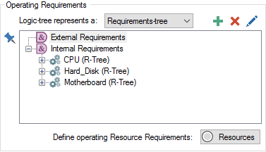
Let’s look at the Computer element’s dialog after we have added RL component nodes for the CPU, Hard Disk and Motherboard:

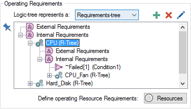
Clicking on the plus sign next to any RL component will display the linked RL element’s requirements tree, and we can add the CPU’s dependency on the CPU fan by adding an RL Component node to the CPU’s logic tree:

Notice how the CPU fan RL Component node also has a plus sign next to it. You can continue to browse and edit the logic trees of other elements down to an arbitrary level of complexity.
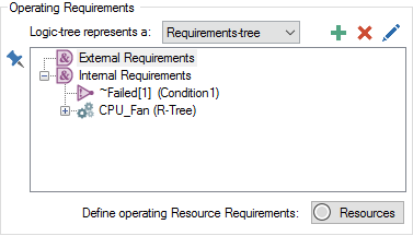
Of course, if we subsequently opened the CPU element, its portion of the logic tree would reflect the changes made within the Computer element:
