 Decision elements allow you to better represent
decision or branching logic in your model.
Decision elements allow you to better represent
decision or branching logic in your model. Decision elements allow you to better represent
decision or branching logic in your model.
Decision elements have either two or three outputs which represent discrete event signals. When the element is triggered, it emits a discrete event signal from one (and only one) of its outputs, depending on a set of user-specified conditions.
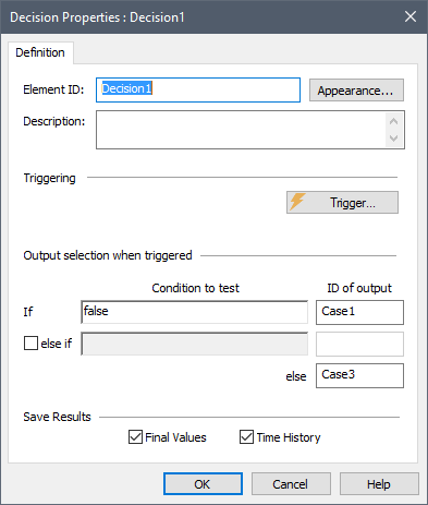
The dialog for a Decision element looks like this:
You first specify when the Decision is to be triggered via the Trigger… button. The Trigger… button in the Decision dialog provides access to a standard Trigger dialog.
When the element is triggered, it evaluates the Condition to test field to determine which output will emit a discrete event signal. By default, there are two discrete event signal outputs, which are named Case1 and Case3. The Condition to test field accepts any condition output or conditional expression.
The ID of output can be modified by the user to any string. (Note, however, that the same rules which apply for element names apply for these IDs.)
To understand how a Decision element works, consider the following example:
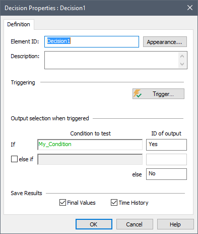
In this case, whenever the element is triggered, GoldSim evaluates the output “My_Condition” (which must be a condition). If this condition is True, a discrete event signal is emitted from the Yes output of the element (in this case, named Decision1.Yes). Otherwise, a discrete event signal is emitted from the No output of the element (in this case, named Decision1.No).
You can add a second condition (and a third output) by clicking the checkbox to the left of the “else if” on the dialog.
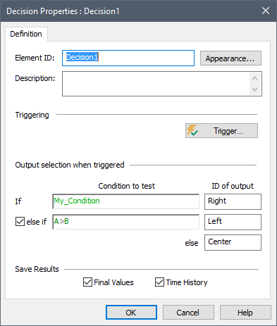
In this case, whenever the element is triggered, if My_Condition is True, a discrete event signal is emitted from the “Right” output of the element (in this case, named Decision1.Right). If My_Condition is False, but A > B, then a discrete event signal is emitted from the “Left” output of the element (in this case, named Decision1.Left). If neither of these conditions is True (i.e., My_Condtion is False and A<= B), a discrete event signal is emitted from the “Center” output of the element (in this case, named Decision1.Center).
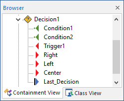
In addition to the two (or three) discrete event signal outputs associated with a Decision element (which you provide a name for), an additional output is produced called Last_Decision. This is a value which takes on one of four values: 0, 1, 2, or 3. Prior to the Decision being triggered, it takes on a value of 0. After a Decision element is triggered, it records which of the three discrete event signal outputs emitted the signal. These are always 1, 2 or 3. Note that even if there are only two outputs, the last event signal output (the “else”) is referred to as output 3.
 Note: A Decision element could be triggered multiple times within a
single update (e.g., a timestep), in which case it would output multiple events.
Note, however, that these events would all be sent to the same output (since the
Condition to test fields are only evaluated once each update).
Note: A Decision element could be triggered multiple times within a
single update (e.g., a timestep), in which case it would output multiple events.
Note, however, that these events would all be sent to the same output (since the
Condition to test fields are only evaluated once each update).
The inputs to a Decision are the trigger(s) and any associated Precedence or Required Conditions, as well as the test conditions. Decisions have up to three discrete event signal outputs, along with the Last_Decision output.
The discrete event signal outputs themselves cannot be saved or viewed as a result.
Note: Element inputs and outputs are
only shown in the browser if you choose to Show Element Subitems (accessed
via the browser context menu by right-clicking in the browser).
The example model Decision.gsm in the General Examples/Events folder of your GoldSim directory (accessed by selecting File | Open Example... from the main menu) contains an example of the use of Decision elements.
Learn more about: